


Scroll compressor processing scheme
Release time:
2022-04-18
Scroll compressor is the latest type of air compressor developed in recent years. Compared with traditional air compressors, it has a series of excellent technical performance, such as simple structure, small size, light weight, low noise, long service life, continuous gas transmission level migration, simple operation and low maintenance cost. It is praised as "no maintenance air compressor" and "new revolutionary air compressor" in the industry, It is the ideal model of air compressor below 50HP.
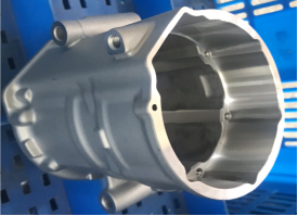
scroll compressor
Scroll compressor is the latest type of air compressor developed in recent years. Compared with traditional air compressors, it has a series of excellent technical performance, such as simple structure, small size, light weight, low noise, long service life, continuous gas transmission level migration, simple operation and low maintenance cost. It is praised as "no maintenance air compressor" and "new revolutionary air compressor" in the industry, It is the ideal model of air compressor below 50HP.
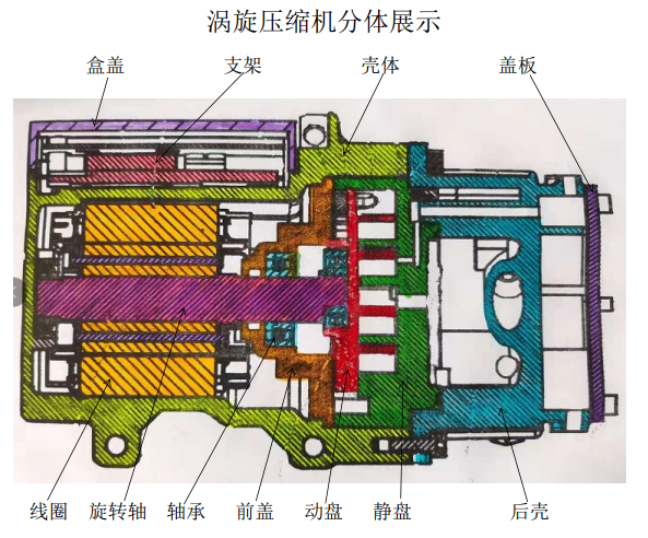
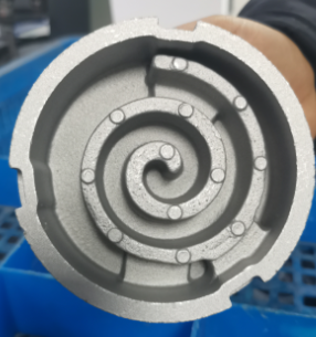
Principle: The dynamic and static vortex disks of two double function equation lines are meshed with each other. Through suction, compression, and exhaust work, the static disk is fixed on the frame, and the moving disk is driven by an eccentric shaft and restricted by an anti-rotation mechanism to rotate on a plane with a small radius around the center of the static disk base circle. The gas is sucked into the periphery of the static disc through the air filter element. With the rotation of the eccentric shaft, the gas is gradually compressed in several crescent-shaped compression chambers composed of dynamic and static interaction, and then continuously discharged from the axial hole of the central part of the static disc.
| Model classification |
|||||||||
| Name |
Corresponding dimension |
E26 |
E27 |
E28 |
E33 |
E34 |
E34 |
E35 |
E40 |
|
Moving disc |
Outer diameter |
78 |
86 |
78 |
81.8 |
84 |
82 |
78 |
81.8 |
| Type line height |
16~20 |
||||||||
| Pin hole |
15~16 |
||||||||
| Clamping mode |
Outer circle |
||||||||
|
|
|||||||||
|
Static disc |
Outer diameter |
100 |
107 |
100 |
Alien |
123 |
108 |
100 |
Alien |
| Type line height |
20~33 |
||||||||
| Pin hole |
3.5~4 |
||||||||
| Clamping mode |
Three points |
Outer circle |
Three points |
Three points |
Outer circle |
Three points |
Three points |
Three points |
|
| Basic process |
|||||||||
|
|
Processing equipment |
||||||||
| Programme |
OP10 |
OP20 |
OP30 |
OP40 |
|||||
|
Shell |
1 |
Horizontal Machining Center |
|
|
|
||||
| 2 |
machining center |
Machining center with four axes |
|
|
|||||
| 3 |
Lathe |
machining center |
Machining center with four axes |
|
|||||
|
Front shell |
1 |
five axis |
|
|
|
||||
| 2 |
turn-milling compound |
turn-milling compound |
|
|
|||||
| 3 |
Lathe |
turn-milling compound |
|
|
|||||
|
Moving disc |
1 |
Lathe |
machining center |
machining center |
machining center |
||||
| 2 |
machining center |
machining center |
turn-milling compound |
machining center |
|||||
| 3 |
Lathe |
Lathe |
special machine machining center |
machining center |
|||||
|
Static disc |
1 |
Lathe |
machining center |
machining center |
machining center |
||||
| 2 |
machining center |
machining center |
turn-milling compound |
machining center |
|||||
| 3 |
Lathe |
Lathe |
special machine machining center |
machining center |
|||||
|
Rear shell |
1 |
Lathe |
five axis |
|
|
||||
| 2 |
Lathe |
machining center |
Machining center with four axes |
|
|||||
| 3 |
Lathe |
turn-milling compound |
Machining center with four axes |
|
|||||
| Bracket |
1 |
machining center |
machining center |
|
|
||||
| Hatch |
2 |
machining center |
machining center |
|
|
||||
| Cover |
3 |
machining center |
machining center |
|
|
||||
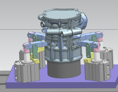
motor case tooling OP10
1: milling plane and drilling, machining parts
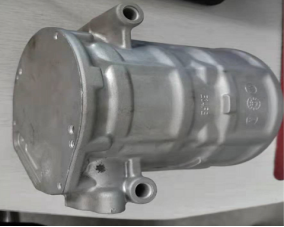
2: four red support, with air-tight detection
3: Four surface compression points, with serrated heads to prevent product deformation during compression.
Inner hole tooling of motor housing OP20
1: boring, machining parts
2: four red support, with air-tight detection
3: yellow two pin point positioning, both have a round pin and an edge pin
4: Four pressing points, with a rotating oil cylinder, rotating pressure
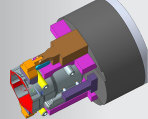
5: Because the positions of the pressing points on the four product surfaces are different, three of them are the same pressing point and the other is not at the same point; When processing different products, replace different pressing blocks; The belt is a serrated head to prevent different product deformation during the pressing process.
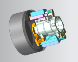
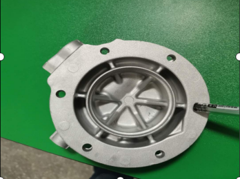
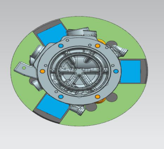
Front shell tooling OP20
1: processing parts: cylindrical end face, positioning pin hole, motor hole, bearing hole.
2: positioning: clamping the outer circle, side angular positioning
3: Three airtight supports, inspection points.

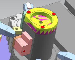
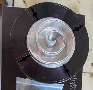
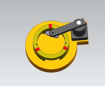
Moving disc OP30: machining of bearing hole surface
Clamp the outer circle, and process the anti-rotation hole, bearing hole and locating pin hole
Pull down and clamp half of the outer circle of the four-jaw clamp, take the end face of the profile line as the reference surface, and position it at the tail of the profile line.
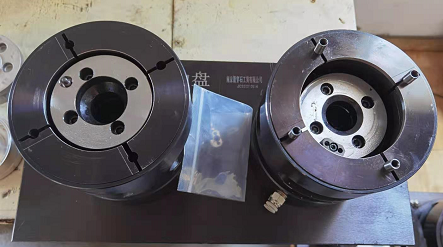
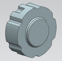
Fixture 3D illustration
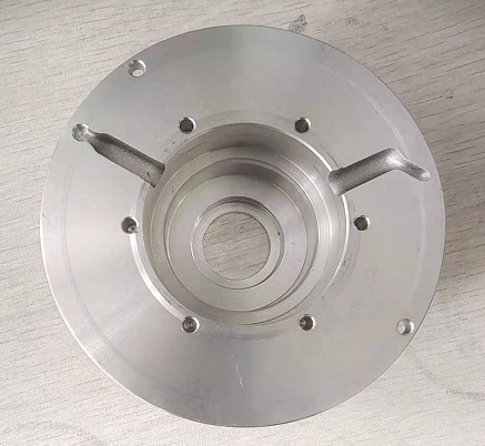
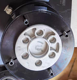
Fixture physical drawing
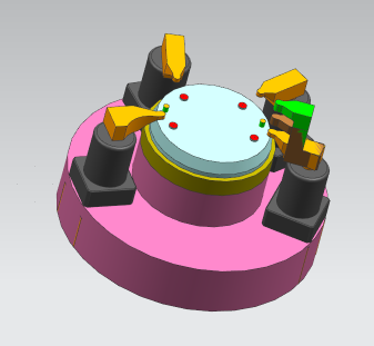
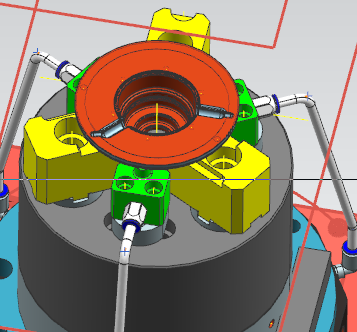
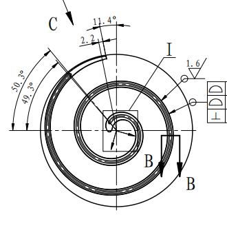
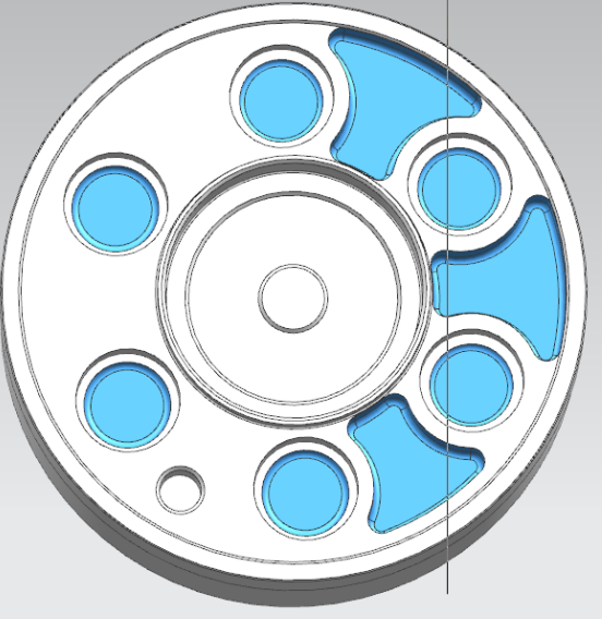
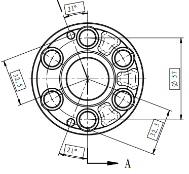
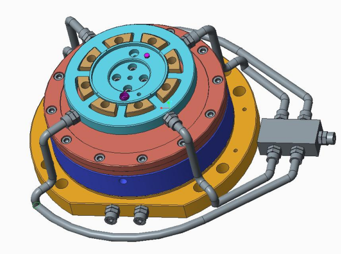
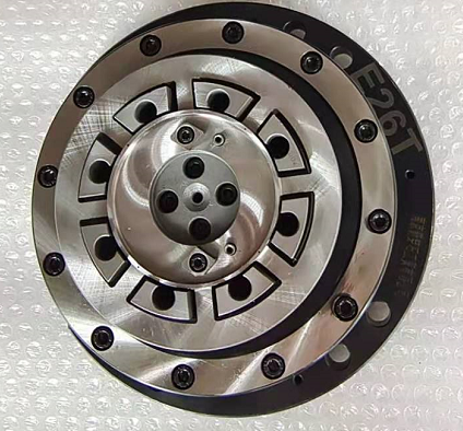
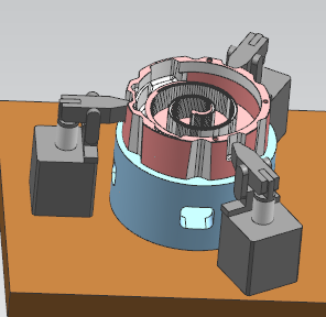
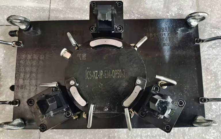
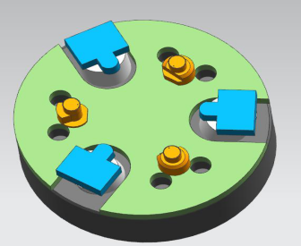
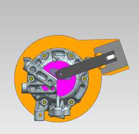
Moving disc OP40-type line processing
Processing method: suck first and then clamp, with airtight detection at the same time
1: The supporting surface has four airtight detection holes at the same time.
2: Positioning: D15.03 round pin positioning, with D15.03 diamond pin for angular positioning.
3: Clamping: floating clamping with D78 excircle.
4: anti-stay: D5 as anti-stay hole.
Fixture 3D illustration
Fixture physical drawing
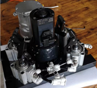
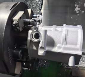
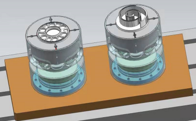
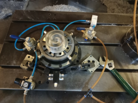
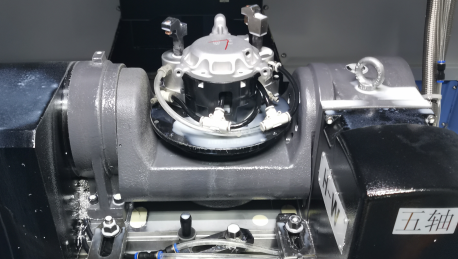
Machine tool processing display
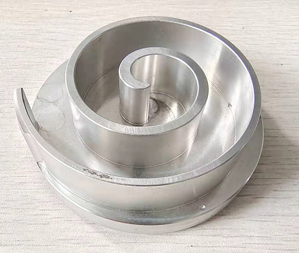
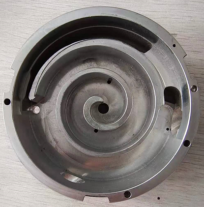
Static Disc OP30-Bearing Hole Surface Machining
Clamp the outer circle, and process the anti-rotation hole, bearing hole and locating pin hole
Pull down and clamp half of the outer circle of the four-jaw clamp, take the end face of the profile line as the reference surface, and position it at the tail of the profile line.

Fixture physical drawing

Static disc OP40
Processing method: hydraulic clamping, with airtight detection
1: Three points on the bottom surface are used as supporting surfaces, and there are three airtight detection holes at the same time; product size
2: positioning: D3.5 round pin positioning, with another D3.5 diamond pin for angular positioning
3: after the first three-point compression, three-jaw clamping, and then open the three-point compression point
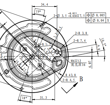
Since there is no 3D drawing of the product, there is no 3D drawing of the fixture for the time being. The following pictures are for reference only.
Back cover front tooling OP10
1: processing parts
2: Three yellow surface supports, with air-tight detection at the same time
3: Three pressing points, the clamping position is the reinforcing rib
Back cover reverse tooling OP20
1: processing parts
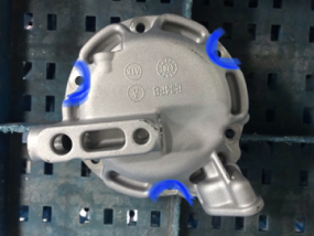
2: three red support, with air-tight detection
3: blue two pin point positioning, both have a round pin and an edge pin
4: two bridge type floating compression mode, with rotating cylinder
The above is our company's full process plan for scroll compressor processing. Everbright insiders are welcome to discuss and exchange. Thank you!
Related Cases
New Da'an

Follow us
Nanjing Arrow-Stone Industry Co. ,Ltd
Telephone: 86 025 84958290
Address: No. 105, Building 8, District 8, Lingxin Market, Jiangning District, Nanjing